
Magnetostrictive sensor outputs: 160 / 161 / 162, 180–185, 190–199
Reading a magnetostrictive displacement sensor model starts with the output code: 160/161/162 on Series 16, 180-185 on Series 18, 190-199 on Series 19. Match the electrical output to the PLC first. This page lists output names only: 160 / 161 / 162, 180–185, 190–199. For stroke, connector, magnet and cable, contact an engineer.
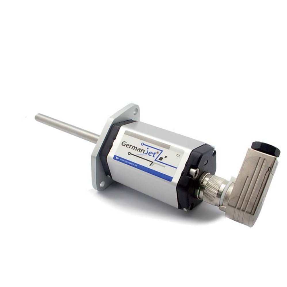
Series 16
Flat-housing in-cylinder. 160 voltage, 161 current, 162 SSI (binary / Gray, RS422). Do not write 162 as 192 — 192 is Series 19 SSI. 162 and 192 are both SSI but belong to different series; writing 162 as 192 picks the wrong mechanics. Contrast: 162 vs 192. See Series 16.
Series 18
External, not pressure-containing. 180 voltage, 181 = 0-20 mA, 182 = 20-0 mA, 183 = Start-Stop, 184 = 4-20 mA, 185 = 20-4 mA. 180–185 are electrical outputs, not floating type / rail type / embedded mechanics. See Series 18.
Series 19
| Output | Interface |
|---|---|
| 190 / 191 / 193 | Voltage / current / Start-Stop |
| 192 | SSI |
| 194 | CANopen |
| 195 | Profibus DP |
| 197 / 198 | EtherCAT / single-M12 EtherCAT |
| 199 | PROFINET |
Mounting variants 19H / 19P / 19D / 19F combine with the outputs above. 192 is still Series 19 SSI — do not mix it with Series 16 code 162.
Series 12
120 analogue voltage, 121 current (16-bit D/A). See Series 12.
After the output is fixed, see the quick-selection table for stroke and mounting. Pros and cons of each output type: output signals compared. Send stroke, output and mounting if anything is unclear.
Engineer's notes
- Match the PLC input first, then pick the output. 181 (0-20 mA) and 184 (4-20 mA) are not interchangeable: 4-20 mA carries a live zero, so a broken wire drops the current below 4 mA and the PLC can flag it directly. A 0-20 mA channel suits legacy cards, but zero and a broken wire look the same. If the logic already tests for a broken wire, take 184. 182 (20-0 mA) and 185 (20-4 mA) are inverted outputs where full scale sits at zero — order the wrong direction and you will add a signal inverter on site.
- Changing the output means changing the model, not a setting. 160 / 161 / 162 are three electrical outputs on the same flat in-cylinder head; 194 (CANopen) and 195 (Profibus DP) are separate order codes. Moving from analogue to fieldbus means re-ordering to the matching head — no firmware flash or DIP switch changes the output.
- Quote the code and the bit count together for SSI. 162 and 192 both offer binary or Gray, 8–32 bits, resolution 1 / 2 / 5 / 10 / 20 / 50 / 100 μm, and must match the high-speed counter card exactly. Ordering "SSI" alone usually means a rework on site.
Frequently Asked Questions
Q: Does Series 16 have SSI?
Yes. Series 16 SSI is 162. 160 is voltage, 161 is current. 192 is Series 19 SSI — do not mix it with 162.
Q: Are 183, 184 and 185 on Series 18 mechanical types?
No. 180–185 are electrical: 180 voltage, 181 = 0-20 mA, 182 = 20-0 mA, 183 = Start-Stop, 184 = 4-20 mA, 185 = 20-4 mA.
Q: What is the difference between 120 and 121 on Series 12?
120 is analogue voltage, 121 is current (16-bit D/A). Do not quote one resolution for the whole series.
Q: How do I choose 191 vs 192 on Series 19?
191 is analogue current, 192 is SSI. CANopen is 194, EtherCAT is 197.
Q: How do I choose between 181 (0-20 mA) and 184 (4-20 mA)?
Pick 184 when the PLC is to detect a broken wire: the 4-20 mA live zero lets the current fall below 4 mA and raise a fault. Pick 181 where a legacy card only accepts 0-20 mA or existing wiring must be reused. Never mix the two on one channel.
Related Products
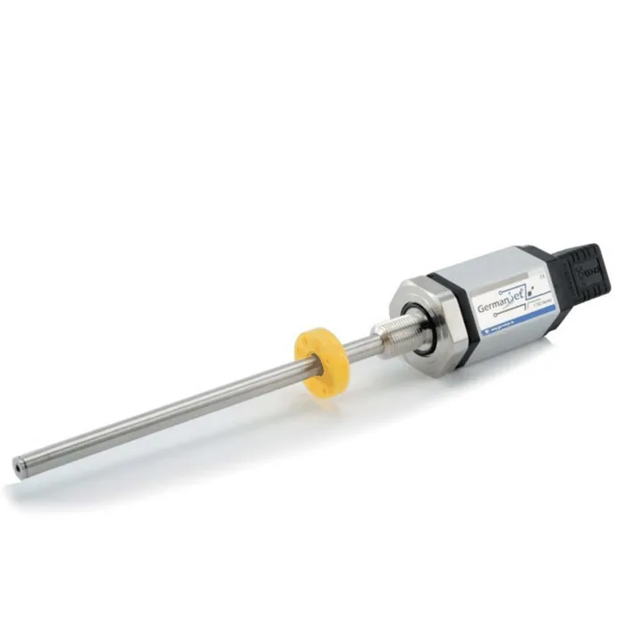
Related Applications
Multi-Industry Application Cases for Magnetostrictive Displacement Sensors
View Details
Series 18 Profile Magnetostrictive Displacement Sensor Application Cases
View Details
Series 12 General-Purpose Magnetostrictive Displacement Sensor Application Cases
View Details