Magnetostrictive Displacement Sensor Quick-Select Table: Stroke, Accuracy, Output and Protection
When reading a magnetostrictive displacement sensor table, accuracy is never one figure for a whole family — it is quoted per range. Selecting a magnetostrictive displacement sensor is most tedious when parameters are flipped among a dozen series. This article compresses the Germanjet full-range core parameters into one quick-reference table: stroke, accuracy, output signal, protection class and positioning in one sentence. Pressure rating, cylinder-cap interface and resolution are written by series from — do not put Series 16’s 530 bar, Series 17’s 600 bar and Series 19 in-cylinder 300/600 bar on the same row. Lock the direction from the table first, then open the corresponding product page for detailed specifications.
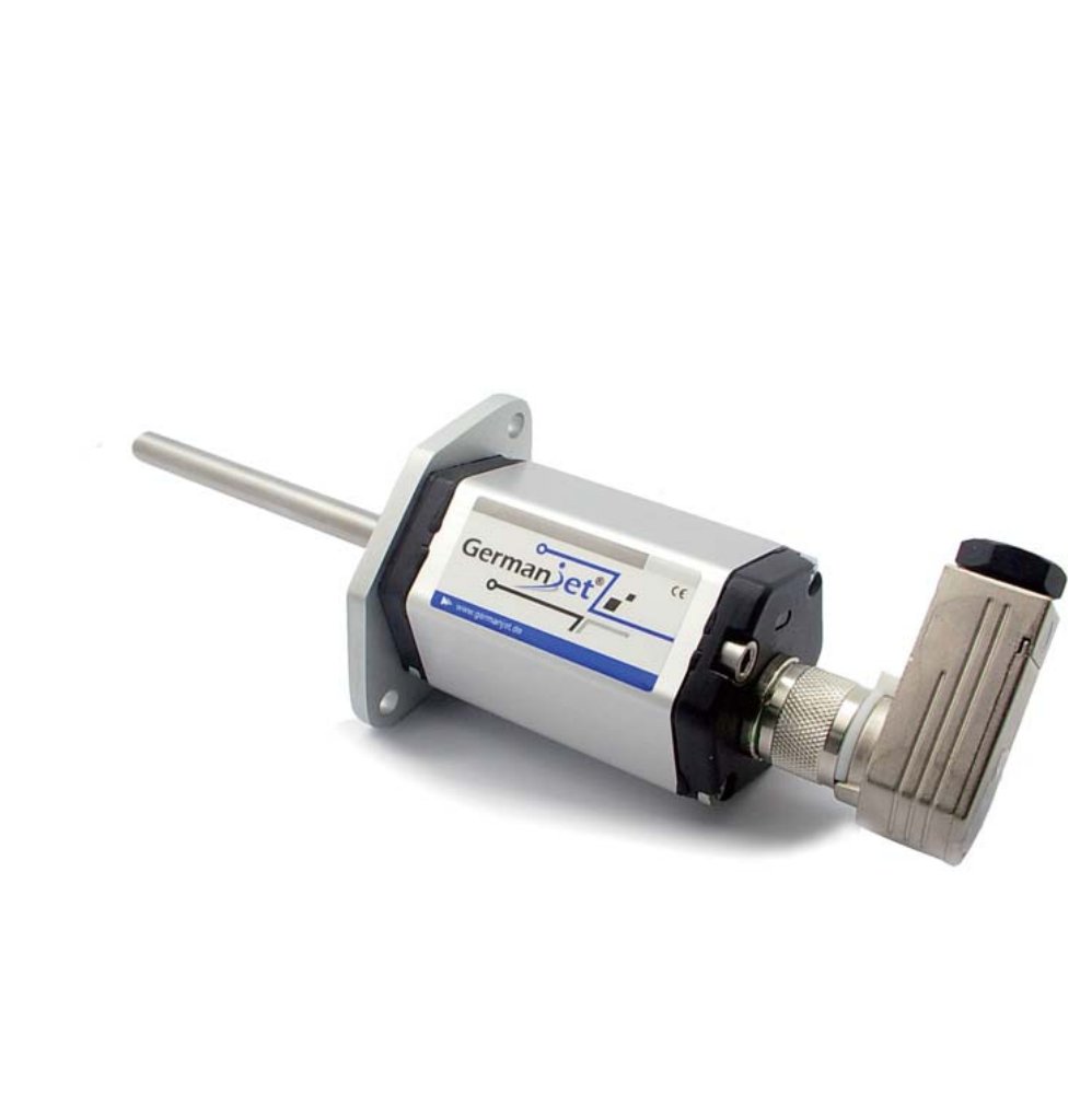
Cylinder-integrated (inside the hydraulic cylinder) at a glance
| Series | Range | Accuracy / resolution | Output | Protection / pressure / interface | Positioning |
|---|---|---|---|---|---|
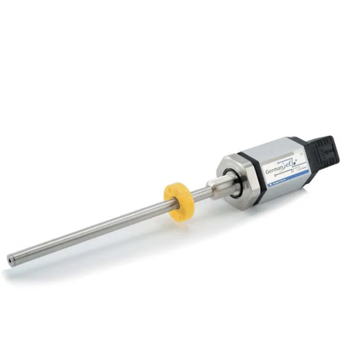
| Series 16 | 50–7600 mm | 16-bit D/A 0.0015% (min. 1 μm) | 160 voltage / 161 current / 162 SSI | IP67; 350 working / 530 bar peak; cap Ø18G7 | Flat electronics housing, cylinder-integrated |
| Series 17 | 100–4000 mm | Analogue resolution infinite (controller A/D); non-linearity <±0.02% FS (min. ±90 μm) | Voltage / current / Start-Stop | IP65/IP67; 350 / 600 bar; cap M18×1.5 | Electronics housing separable from the pressure tube |
| 19H | 75–475 mm | 16-bit D/A | Analog / digital / fieldbus | IP67; 300 working / 600 bar peak | Cylinder-integrated, all stainless steel |
| 16R/16T | 75–2200 mm | 16-bit D/A | Dual / triple independent outputs | IP67; 350 / 530 bar; Ø18G7 | Dual / triple redundancy, safety-critical |
| 16E | 75–7600 mm | 16-bit D/A | Single / redundant output | IP68; peak as Series 16, 530 bar | Harsh environment, salt-spray resistant |
| 17EX | 50–4000 mm | Same analogue wording as Series 17 | Multiple protocols (including fieldbus) | IP67, intrinsically safe; 350 / 600 bar; M18×1.5 | Zone 0/1/2 hazardous areas |
Piston-rod bore lower limit is ≥12.7 mm (Ø10 rod) on all of the above. Ø13 mm is the Series 17 cylinder-cap through-hole, not the piston-rod bore.
External (rod / rail) at a glance
| Series | Range | Accuracy / resolution | Output | Protection | Positioning |
|---|---|---|---|---|---|
| Series 12 | 50–2500 mm | 120 infinite resolution; 121 is the 16-bit D/A | Analogue voltage/current + Start-Stop | IP65/IP67, not pressure-containing | Wall-thickness-control servo cylinder end cap, DIN 43650 |
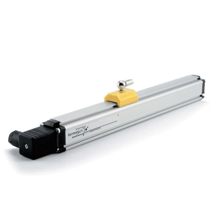
| Series 18 | 50–4000 mm+ | Analogue resolution infinite; non-linearity <±0.02% FS (min. ±90 μm) | Analog + Start-Stop | IP65/IP67, not pressure-containing | External rod / rail; four-pin voltage type: see wiring red lines |
| 19P | 125–4050 mm | 16-bit D/A | Analog / digital / fieldbus | IP67 | External rod, aluminium profile housing |
| 19D | 75–475 mm | 16-bit D/A | Analog / digital / fieldbus | IP67 | Split-type, electronics housing mounted remotely |
| 19F | 2500–7600 mm | Analogue 16-bit D/A | Analog / digital / fieldbus | IP67; front dead zone 50/130 mm | Flexible tube, non-ferromagnetic guide tube |
Mobile hydraulics at a glance
| Series | Range | Accuracy / resolution | Output | Protection | Positioning |
|---|---|---|---|---|---|
| Series 13 | 50–2500 mm | Per ordered model | Voltage / analog / CANopen | IP68→IP69K | Mobile machinery, 25 g vibration |
| 13C | 50–2500 mm | Per ordered model | 0.1-4.9 V voltage | IP68→IP69K | Compact, low power, voltage output |
| 13R | 75–450 mm | Per ordered model | Dual-channel redundant output | IP68→IP69K | Redundant output, safety-critical |
Fieldbus types at a glance (Series 19 digital interfaces)
| Series | Protocol | Features | Interface |
|---|---|---|---|
| 191 | Analog | 16-bit D/A, dual-magnet minimum 76 mm | D60 6-pin M12 |
| 192 | SSI | Absolute position, 8-32 bit | D70 7-pin |
| 194 | CANopen | DS-301, 20-1000 kbit/s | D60 6-pin |
| 195 | Profibus | DP, up to 12 Mbit/s | D53 dual M12 |
| 197 | EtherCAT | DC synchronisation, 100 Mbit/s | D56 daisy-chain |
| 198 | EtherCAT | Single M12 8-pin integrated | M12 8-pin |
| 199 | PROFINET | RT/IRT, encoder Profile 4.1 | D56+M8 |
Lock the series in three steps
Step 1: decide the mounting method — cylinder-integrated choose 16/17/19H, external rod choose 12/18/19P/19D, extra-long stroke choose 19F, mobile machinery choose Series 13. Step 2: decide the output — Series 16 can be 160/161 analogue or SSI; analogue is also 191 or Series 12/18 codes, fieldbus 194/195/197/199 by PLC protocol, safety redundancy 16R/16T/13R. Step 3: check pressure rating and interface by series — Series 16 is 350/530 bar + Ø18G7, Series 17 is 350/600 bar + M18×1.5, 19H is 300/600 bar. Lock mounting first, then output, then check the pressure rating and cap thread — do not quote one resolution for the whole series. Detailed parameters are on the corresponding product page.
Frequently Asked Questions
Q: What is the fastest way into the selection process?
Lock the series in three steps. Step one, the mounting method: cylinder-integrated choose 16/17/19H, external rod choose 12/18/19P/19D, extra-long stroke choose 19F, mobile machinery choose Series 13. Step two, the output: Series 16 can be 160/161 analogue or 162 SSI, analogue is also 191 or Series 12/18 codes, fieldbus is 194/195/197/199 by PLC protocol, and safety redundancy is 16R/16T/13R. Step three, check pressure rating and interface by series. Working back from the application to the mounting form and then looking up the model is far quicker than flipping through a dozen series.
Q: How do I check the pressure rating and cylinder-cap interface?
By series, never on one row: Series 16 is 350 bar working and 530 bar peak with a cap of Ø18G7; Series 17 is 350 and 600 bar with M18x1.5 on the cap; 19H in-cylinder is 300 and 600 bar. Also keep bore and through-hole apart: the piston-rod bore lower limit is at least 12.7 mm across these series with a Ø10 rod, whereas Ø13 mm is the Series 17 cylinder-cap through-hole, not the piston-rod bore. Swapping those two figures means the cylinder is machined wrongly.
Q: Which fieldbus protocols are available?
The Series 19 digital interfaces cover 194 CANopen (DS-301, 20 to 1000 kbit/s, D60 6-pin), 195 Profibus (DP, up to 12 Mbit/s, D53 dual M12), 197 EtherCAT (DC synchronisation, 100 Mbit/s, D56 daisy-chain), 198 EtherCAT (single M12 8-pin integrated) and 199 PROFINET (RT/IRT, encoder Profile 4.1, D56+M8). There is also 192 SSI for absolute position, 8 to 32 bit, and 191 analog.
Q: Which series suits extra-long stroke, harsh environment or hazardous areas?
For extra-long stroke choose the 19F flexible tube, 2500 to 7600 mm, noting its front dead zone of 50 mm for strokes below 8000 mm and 130 mm above. For a salt-spray resistant harsh environment choose 16E, 75 to 7600 mm, IP68, with peak pressure as Series 16 at 530 bar. For mobile machinery needing high protection choose Series 13, IP68 to IP69K with 25 g vibration. For hazardous areas choose the 17EX intrinsically safe type, rated for Zone 0, 1 and 2.
Related Products
Related Applications
Multi-Industry Application Cases for Magnetostrictive Displacement Sensors
View Details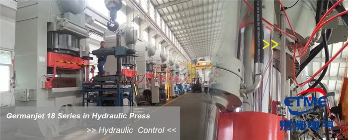
Series 18 Profile Magnetostrictive Displacement Sensor Application Cases
View Details
Series 16 Hydraulic Rod Magnetostrictive Displacement Sensor Application Cases
View Details