
Installing Magnetostrictive Displacement Sensors in Practice: Position Magnet, Zero Point, Noise Immunity
A magnetostrictive displacement sensor is itself maintenance-free, but how well it is installed decides whether it stays that way. Of ten abnormal readings on site, seven or eight come from mounting and cabling, not from a failed sensor. This article covers the practical points that are most often overlooked.
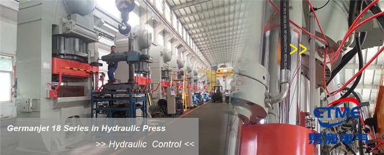
Position-magnet mounting: concentricity and clearance are critical
The position magnet (permanent magnet) rides on the outside of the measuring rod and senses position by magnetic field. It and the rod must be coaxial, with uniform clearance — check even radial clearance and no scuff when hand-rotated; eccentricity drifts the readings over a local stroke. If the magnet is mounted off-centre on the piston rod, or rubs the measuring rod, the signal will fluctuate; in severe cases the echo is lost altogether.
- There must be a sensible clearance between the magnet inner diameter and the rod outer diameter — neither so loose that it wobbles radially, nor so tight that it wears the rod;
- The magnet must be firmly fixed; on machines with high vibration, add an anti-loosening arrangement so the magnet cannot shift axially;
- The magnet must not travel beyond the end of the rod's effective measuring range, or the portion beyond cannot be read.
Zero calibration: establish the datum before you trust the reading
After installation, the first task is to calibrate zero. Most controllers support "set current position as zero" or an offset compensation. Recommended practice:
- Set zero at the machine mechanical zero (for example with the cylinder fully retracted);
- Cross-check the sensor reading against a mechanical scale and confirm the full-scale correspondence;
- Record the zero offset so that a later change of type or reinstallation has a documented baseline;
- Set zero only after the machine reaches thermal equilibrium; calibrating cold and running hot is a classic source of offset.
Cabling and screening: seven-tenths of interference starts here
Signal cables dislike running face-to-face with power cables. Rules of thumb:
- Run signal and power cables in separate trunking, at least 20 cm apart; where they must cross, cross at right angles;
- Screen earthing depends on cable type: single-end earth analog signal cables (usually at the control-cabinet side) to avoid earth loops from potential difference; fieldbus cables (CANopen / Profibus / EtherCAT) should have 360° bonding at both ends when the two ends are reliably at the same potential, so that high-frequency interference has a path to dissipate;
- Use twisted pair for bus cable, and tighten connectors — a loose contact invites more interference than a long run.
Special points for in-cylinder mounting
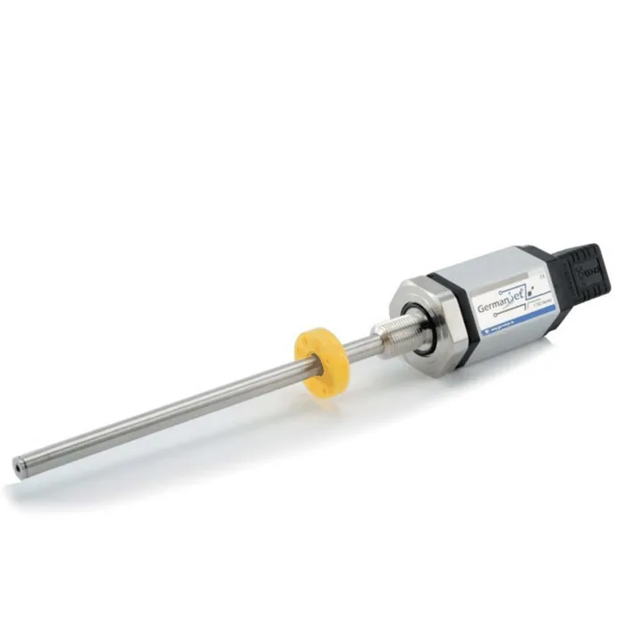
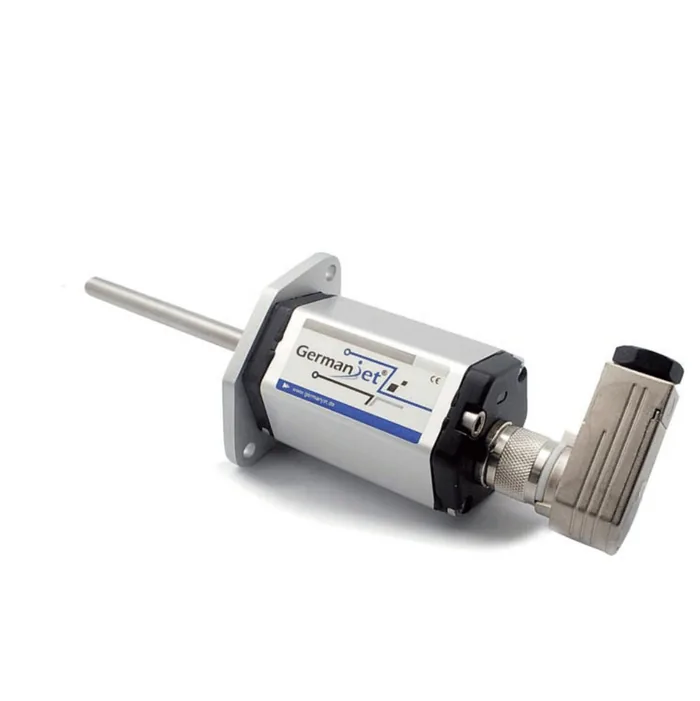
For sensors built into a cylinder, such as the Series 17 hydraulic-cylinder integrated type and the Series 16 hydraulic profile type, also note:
- Confirm that the cylinder bore diameter matches the sensor outer diameter; the bore must match the series: Series 16 cap Ø18G7 / rod Ø10 / piston bore ≥12.7 mm; Series 17 cap M18×1.5 / through-hole Ø13 mm / piston bore ≥12.7 mm;
- Oil cleanliness must be adequate; debris wearing the rod shortens life;
- The pressure rating (350/530 bar (Series 16), 350/600 bar (Series 17), 300/600 bar (Series 19 in-cylinder)) must cover system peak pressure; do not size on working pressure alone;
- Deep-hole straightness matters more than bore finish, because the rod never touches the wall.
Practical tips for engineers
- For in-cylinder mounting, piston-rod bore lower limit is ≥12.7 mm (Ø10 rod). Series 17 also has a Ø13 mm through-hole + M18×1.5 on the cylinder cap; Series 16 uses Ø18G7. Do not mix pressure ratings: Series 16/16R is 350 bar working / 530 bar peak, Series 17/17EX is 350/600 bar, Series 19 in-cylinder is 300/600 bar.
- The sensor rod inside the cylinder should be protected against wear.
- Series 19 in-cylinder types are rated 300 bar, 600 bar peak; use these figures for selection and pressure testing.
Frequently Asked Questions
Q: The sensor is maintenance-free, so why do readings still drift on site?
Of ten abnormal readings on site, seven or eight trace back to mounting and cabling rather than a failed sensor. The two most common causes are an off-centre position magnet and signal cable run face-to-face with power cable.
Q: What counts as correct position-magnet mounting?
The magnet and the measuring rod must be coaxial with uniform clearance. Check even radial clearance and no scuff when hand-rotated. Eccentricity or rubbing makes the signal fluctuate and in severe cases loses the echo altogether, and local scuffing drifts the reading over part of the stroke. The magnet must also not travel beyond the end of the rod's effective measuring range, and on high-vibration machines it needs an anti-loosening arrangement so it cannot shift axially.
Q: When should zero be calibrated, and why not on a cold machine?
Set zero only after the machine reaches thermal equilibrium; calibrating cold and running hot is a classic source of offset. Set zero at the mechanical zero, for example with the cylinder fully retracted, cross-check the reading against a mechanical scale to confirm the full-scale correspondence, and record the zero offset so a later change of type or reinstallation has a documented baseline.
Q: Should the cable screen be earthed at one end or both?
It depends on the cable type. Earth analog signal cables at one end, usually the control-cabinet side, to avoid earth loops from potential difference. Fieldbus cables such as CANopen, Profibus and EtherCAT should be bonded 360 degrees at both ends when the two ends are reliably at the same potential, so high-frequency interference has a path to dissipate. Either way, keep signal and power cables in separate trunking at least 20 cm apart, crossing at right angles where they must cross.
Q: What must I confirm before mounting into a hydraulic cylinder?
First the bore: Series 16 uses a cap of Ø18G7 with a Ø10 rod and a piston-rod bore of at least 12.7 mm; Series 17 uses M18x1.5 on the cap, a Ø13 mm through-hole and the same 12.7 mm piston bore minimum. Then the pressure rating against system peak, never working pressure alone: Series 16 is 350 bar working and 530 bar peak, Series 17 is 350 and 600 bar, Series 19 in-cylinder is 300 and 600 bar. Oil cleanliness must also be adequate, and the rod needs protection against wear.
Related Products
Related Applications
Multi-Industry Application Cases for Magnetostrictive Displacement Sensors
View Details
Series 16 Hydraulic Rod Magnetostrictive Displacement Sensor Application Cases
View Details
Series 17 Hydraulic Cylinder Integrated Magnetostrictive Displacement Sensor Application Cases
View Details