
Magnetostrictive Displacement Sensor Calibration: Writing Dead-Zone Compensation into Firmware
Factory calibration is the process of writing each magnetostrictive displacement sensor's individual differences into firmware; linearisation compensation then corrects the deviation of the full-stroke reading from the ideal straight line (including dead-zone handling). These two steps are what put the stated non-linearity inside the specification, rather than relying on theoretical design alone.

What calibration does
Calibration is done per unit, not as one parameter set per model. Each unit's waveguide length, speed of sound and electronics-head delay differ slightly. At despatch, "true position vs. measured reading" is taken at several standard position points, and that unit's unique compensation parameters — zero offset, span coefficient and temperature-drift curve — are calculated and written to the electronics-head memory.
Linearisation: correcting non-linearity
The raw reading deviates from the ideal straight line; linearisation uses fitting and look-up tables to press the full-stroke deviation inside the stated non-linearity. For the definition and reading of non-linearity see the three accuracy terms. An illustrative comparison of the raw reading against the calibrated reading before and after pressing into spec:
| Stage | Reading deviation | Notes |
|---|---|---|
| Raw reading | Includes individual error | Uncompensated |
| After calibration | Pressed inside the specification | Compensation parameters written |
Dead-zone compensation
The measuring dead zones at both ends (see measuring dead zones) cannot be linearised into the active range; the calibration process treats the dead-zone segments specially in firmware so that readings inside the effective range stay continuous and stable.
Engineering meaning
- Factory calibration is done on each unit, not "one parameter set per model";
- Calibration solves the sensor's individual deviation; the mechanical zero offset still has to be set once at installation (see zero-calibration steps);
- Methods for synchronised calibration of several sensors are in synchronised calibration of multiple sensors.
Overall installation and commissioning is in installation in practice; the relationship between calibration and accuracy figures is recapped in resolution, repeatability and non-linearity. Factory calibration sets the sensor's own accuracy; the whole chain still inherits the error of the PLC analog input card, so a coarse card caps practical accuracy well before the sensor itself.
Practical tips for engineers
- Analog outputs are factory-calibrated slightly wider than the nominal stroke; after installation the machine must be recalibrated.
- Two-point method: Slope = actual displacement ÷ (stroke-end reading − zero reading); Datum = Slope × zero reading; machine position = (Slope × current reading) − Datum.
- Example: zero reading 0.2 V, reading after moving 98 mm is 9.5 V → Slope = 98÷(9.5−0.2) = 10.537, Datum = 10.537×0.2 = 2.106.
Frequently Asked Questions
Q: Is factory calibration done on every unit?
Yes. Individual differences are calibrated unit by unit, not as one parameter set per model.
Q: What does linearisation solve?
It corrects the non-linear deviation of the full-stroke reading from the ideal straight line, pressing it inside the stated specification.
Q: Is a site zero still needed after calibration?
Yes. The mechanical zero offset still has to be set once at installation.
Related Products
Related Applications

Series 12 General-Purpose Magnetostrictive Displacement Sensor Application Cases
View Details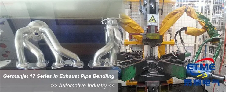
Series 16 Hydraulic Rod Magnetostrictive Displacement Sensor Application Cases
View Details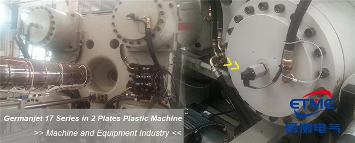
Series 17 Hydraulic Cylinder Integrated Magnetostrictive Displacement Sensor Application Cases
View Details