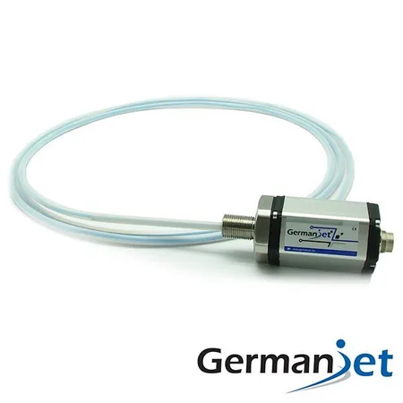
Displacement Sensor Parameters Explained: Compare Millimetres at One Range
Displacement sensor parameters explained starts with one conversion rather than one comparison: turn %FS into millimetres. Non-linearity is quoted as %FS, so the same 0.02% FS is ±0.02 mm on a 100 mm stroke but ±0.8 mm on a 4000 mm stroke — a factor of 40. The first rule of reading a datasheet is therefore blunt: compare absolute error at one range only. If the ranges differ, convert to millimetres before saying a word.

Turn %FS into millimetres first
Put the common strokes next to the common non-linearity steps and the absolute error is no longer hidden:
| Stroke | 0.01% FS | 0.02% FS | 0.05% FS |
|---|---|---|---|
| 100 mm | ±0.01 mm | ±0.02 mm | ±0.05 mm |
| 300 mm | ±0.03 mm | ±0.06 mm | ±0.15 mm |
| 1000 mm | ±0.1 mm | ±0.2 mm | ±0.5 mm |
| 2000 mm | ±0.2 mm | ±0.4 mm | ±1.0 mm |
| 4000 mm | ±0.4 mm | ±0.8 mm | ±2.0 mm |
| 7600 mm | ±0.76 mm | ±1.5 mm | ±3.8 mm |
The table answers a common question directly: to hold ±0.1 mm over a 4 m stroke, 0.02% FS is not enough — change the accuracy class or change the measuring principle, rather than tuning controller parameters to compensate. In the other direction, at a 100 mm stroke even 0.05% FS is ample, and extra money buys nothing on site.
Three accuracy terms, three different jobs
These three are the ones most often read as if they were the same thing:
- Resolution: the smallest step that can be distinguished, commonly 1 / 2 / 5 / 10 / 20 / 50 / 100 μm. It says how finely the reading can be sliced, not how accurate it is.
- Repeatability: whether the reading returns to the same value when the axis comes back to the same position, typically of the order of ±0.002 mm. This is what a closed loop lives on.
- Non-linearity: the maximum deviation of the real curve from the ideal straight line over the full stroke, typically <0.02% FS. It decides whether the millimetre number on the display is the right one. The distinctions are set out in The Three Accuracy Terms of Magnetostrictive Sensors.
One more point deserves its own line: high resolution does not mean a steady reading. A last digit that keeps flickering is usually quantisation steps plus the noise floor — how to classify and handle it is in Last-Digit Jitter on a Magnetostrictive Displacement Sensor.
Three premises that are usually missed
Every accuracy figure carries premises, and comparisons collapse when they are not aligned:
- Temperature interval: the ambient range the figure applies to, whether a temperature coefficient is included, and whether operating and storage temperatures have been mixed up — see Operating vs Storage Temperature.
- Protection class: IP65 / IP67 / IP68 / IP69K correspond to quite different test conditions; do not read the number alone — see IP65 to IP69K: What the Ratings Really Mean.
- Pressure basis: whether an in-cylinder rating is static pressure or includes peaks decides whether the cylinder can use it at all — see Rate an In-Cylinder Sensor by Pressure Peak.
Reading order: five steps
- Fix the stroke first: include the margin for the dead zones at both ends — see Dead Zones at Both Ends.
- Then decide which accuracy matters: closed loops live on repeatability; absolute accuracy is the non-linearity converted into millimetres.
- Align the three premises: temperature, protection and pressure. If they do not match, comparing accuracy is pointless.
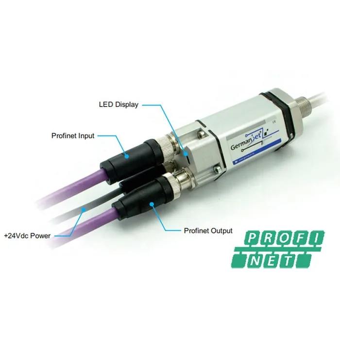
- Choose the output last: match the channels the PLC actually has — see Which Bus My PLC Supports.
- Write it into the register: stroke, output, connector and magnet specification together, so a future replacement is not bought wrong — see Spare-Parts Check Across Three Layers.
The chain that closes it
Put together, reading a datasheet is a chain: stroke → absolute error at that stroke → whether repeatability meets the process tolerance → whether temperature, protection and pressure premises cover the site → whether the output matches the controller. Only when the chain is complete have the parameters actually been read, rather than one resolution figure remembered. Common wording traps in datasheets are in Read a Datasheet Without Falling for Its Traps.
Frequently Asked Questions
Q: Can accuracy figures from different strokes be compared directly?
No. Non-linearity is quoted as %FS, so the same 0.02% FS is ±0.02 mm at 100 mm but ±0.8 mm at 4000 mm — a factor of 40. Convert to absolute error at one stroke before comparing.
Q: Does high resolution mean high accuracy?
No. Resolution is only the smallest distinguishable step (1 / 2 / 5 / 10 / 20 / 50 / 100 μm classes). Repeatability decides whether a closed loop returns to the same position, and non-linearity decides whether the absolute number is right.
Q: Which premises are most often overlooked?
Three: the temperature interval the accuracy figure applies to (and whether a temperature coefficient is included), the test conditions behind an IP rating, and whether an in-cylinder pressure rating is static or includes peaks.
Q: Once the figures are aligned, what is the selection order?
Stroke including dead-zone margin → absolute error at that stroke → repeatability against process tolerance → temperature, protection and pressure coverage → output matching the controller. Then record stroke, output, connector and magnet in the spare-parts register.
Related Products
Related Applications
Multi-Industry Application Cases for Magnetostrictive Displacement Sensors
View Details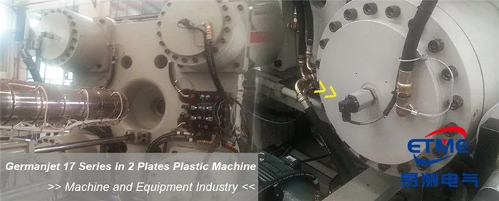
Series 17 Hydraulic Cylinder Integrated Magnetostrictive Displacement Sensor Application Cases
View Details
Series 19D Split-Type Process Displacement Sensor Application Cases
View Details